What is a Network Topology Diagram?
A network topology diagram is a visual representation of the structure of a network, including its physical and logical arrangement of nodes and connections.
The diagram can depict the physical structure, meaning the actual physical arrangement of the components that make up the network, including:
- Devices
- Routers
- Cables
It can also depict the logical structure, which is the way information flows through a network. The logical structure includes components such as:
- Subnets
- Routers
- Firewalls
A network’s physical and logical topology diagrams may look similar, but they could also be completely different—it all depends on the setup of the individual network.
Why Make a Network Topology Diagram?
Having a network topology diagram as part of your documentation helps IT teams do their job in several important ways, such as:
- Troubleshooting network problems more easily
- Getting new team members up to speed quickly during onboarding
- Planning expansion of the network or proposing infrastructure changes
Plus, in larger networks especially, keeping track of all the components of a network can be a challenging task. Maintaining an up-to-date network topology diagram makes that task easier.
If your IT service desk is based in Jira, ITSM documentation with resources such as network topology diagrams located in a Confluence knowledge base can help your team deliver fast, efficient service. Gliffy makes it easy to create these visuals directly in Confluence!
Keep reading to learn more about different types of network topology diagrams, or find the section that’s relevant to your network:
Back to topWhat Are the Types of Network Topology?
Not every network is built the same way. That’s because the structure of a network influences its cost and function, so IT leadership teams make important decisions about which network topology best fits their organization’s needs.
Although every individual network will be structured a little differently, there are several common network topologies that form the baseline of most networks. The topology of your network will determine the shape of your diagram.
Star Topology
The star is one of the most common network topologies. In this topology, each node of the network is individually connected to a central hub, which manages and controls the entire network. Together, the nodes extend from that central hub like the points of a star.
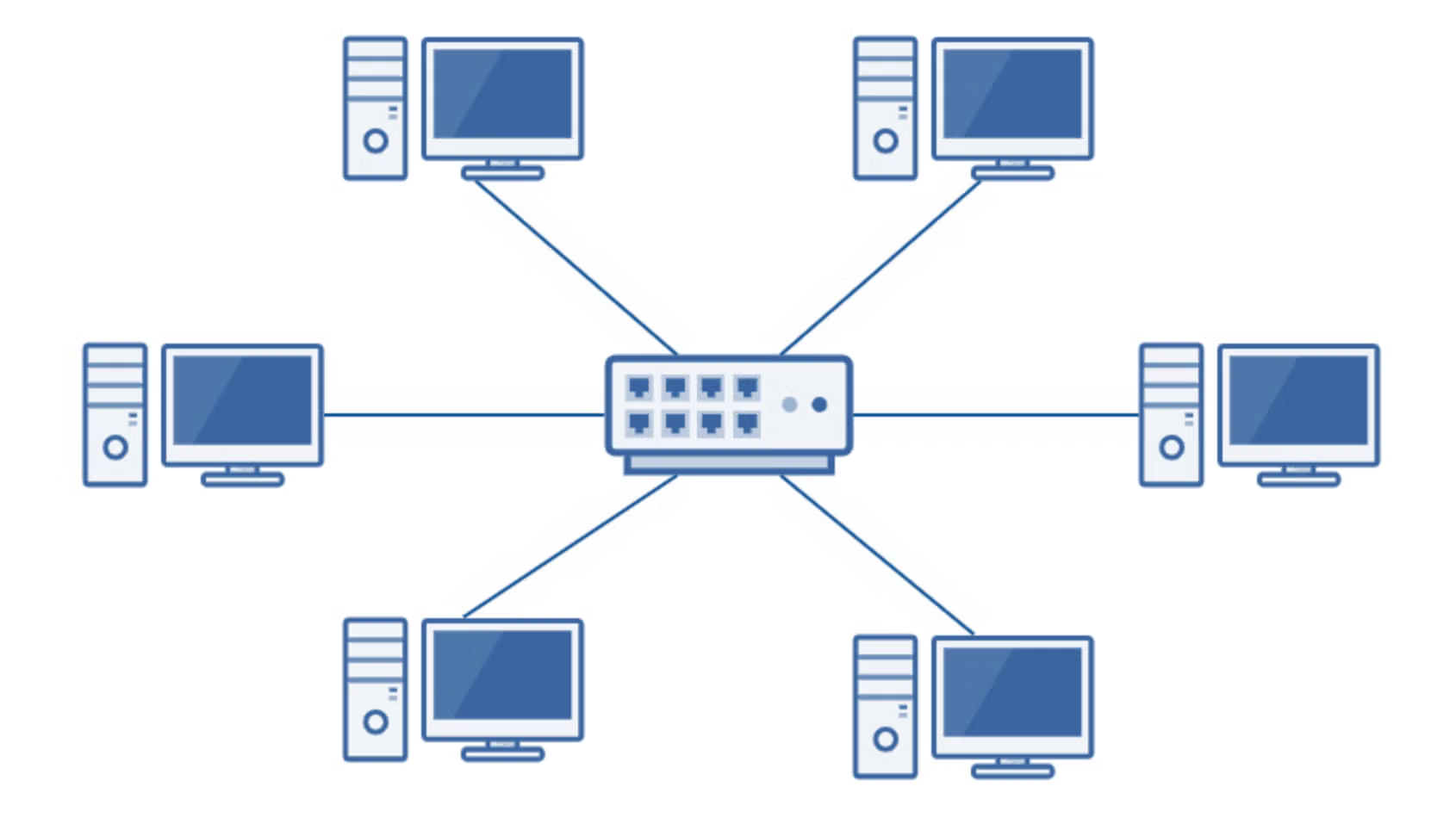
It’s easy to manage a network with the star topology because it can be done through one central hub, and because you can add or remove devices without taking the whole system offline. This type of network is also typically secure and stable because all nodes are connected independently to the hub, so a fault in one node won’t take down the rest of the network.
However, the downside is that the functioning of the network depends on the central hub being active. It also can be one of the more expensive topologies because of the cables and connectors required, and the fact that the central hub must be compatible with all the nodes and connectors in the network.
Bus or Linear Topology
Bus topology, also called linear topology, is one of the simpler topologies, making it a cost-effective choice for smaller networks. It consists of a central medium (the “bus”), one line with two endpoints, which all the nodes are connected to.
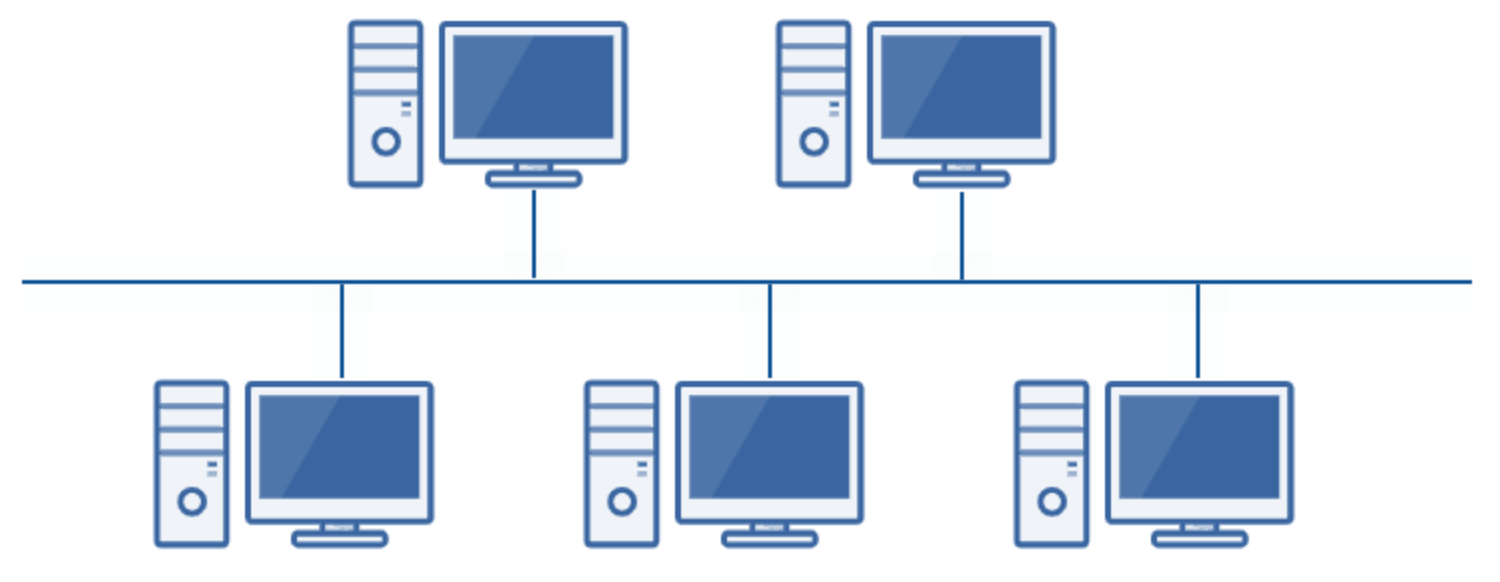
It’s easy to configure and requires less cable length than some other topologies, but if there’s a problem with the central bus, the whole network goes down with it, and that can cause difficulties with identifying issues. Additionally, the performance of the network can be reduced as more devices are added to the network, stretching the bandwidth.
Ring Topology
In a ring topology, each node is connected to two others to form a closed network in the shape of a ring. Information is sent from one node to another through the ring until it reaches its destination.
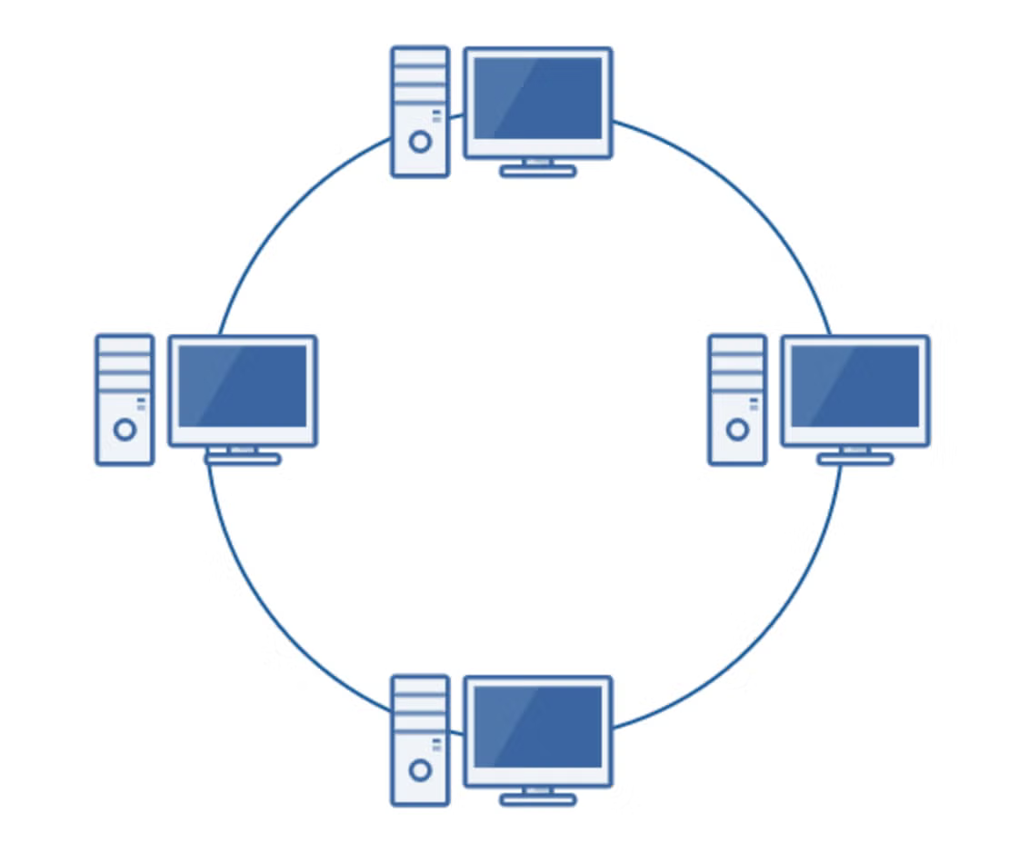
This topology is also cost-effective and may perform faster than bus topology, and it’s relatively easy to identify issues when they arise, but its downside comes in its vulnerability.
A fault in one device or in the cable can disrupt the whole network, and it can be an inconvenience to add, remove, or reconfigure devices because it requires taking the system offline for a brief time. Because of this, ring topology is more difficult to scale effectively compared to some of the other topologies.
Mesh Topology
There are two forms of mesh topology. One is full mesh (pictured below), where every node is interconnected. Partial mesh, on the other hand, means nodes are only connected to the other nodes that they interact with most often.
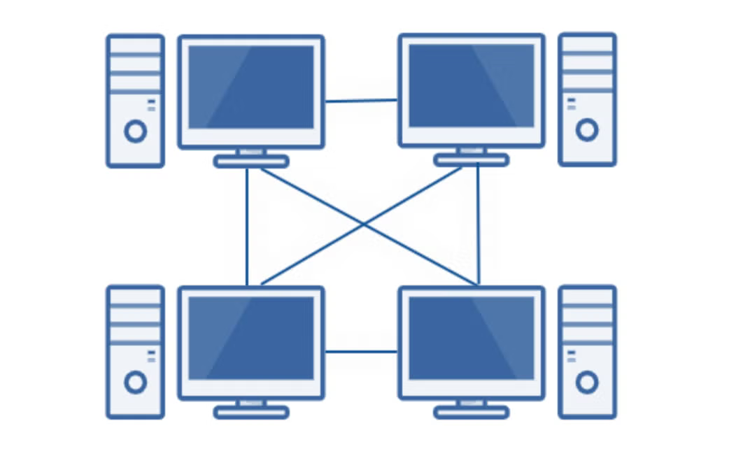
Full mesh topology is extremely stable and high-performing. The high level of interconnectivity also means it’s very unlikely that a fault in one node will impact the other nodes to a great extent.
However, mesh topology networks are cost-intensive and time-consuming both to set up and to maintain. Because of this, mesh topology is usually reserved for critical networks. It would simply be ineffective and expensive to manage this kind of topology for a larger network.
Tree Topology
In a tree topology, the network is made up of a “trunk,” or backbone connection, that connects to mid-level hubs (“branches”), which then are connected out to nodes (“leaves”). Technically, tree topology could actually be considered a hybrid topology of bus and star, but it’s distinct enough to make up its own category.
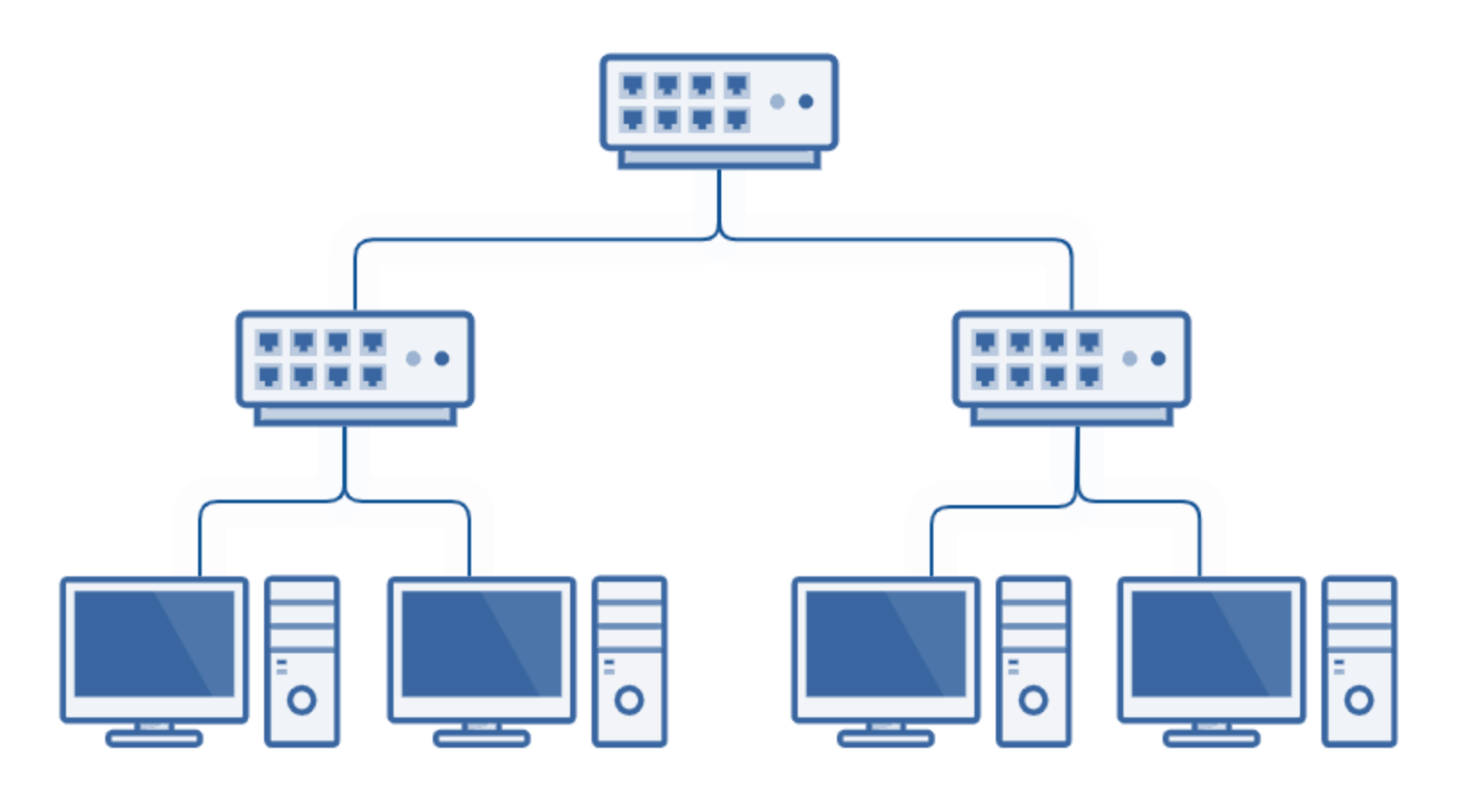
Tree topology is ideal for large networks, especially those where nodes are grouped together. It’s easy to scale, and parts of the “tree” will likely be unaffected by damage to another part of the network. It’s also easy to isolate and troubleshoot issues because each branch can be individually assessed.
However, the entire network depends on the root node. If there’s a failure in the central hub, the branches will disconnect from each other. Tree topology networks can also be difficult to configure and maintain because of their hierarchical complexity and the fact that they require more cabling than some of the alternatives.
Hybrid Topology
Finally, the topology of a network can be a combination of any of the other types in whichever way fits an organization’s need.
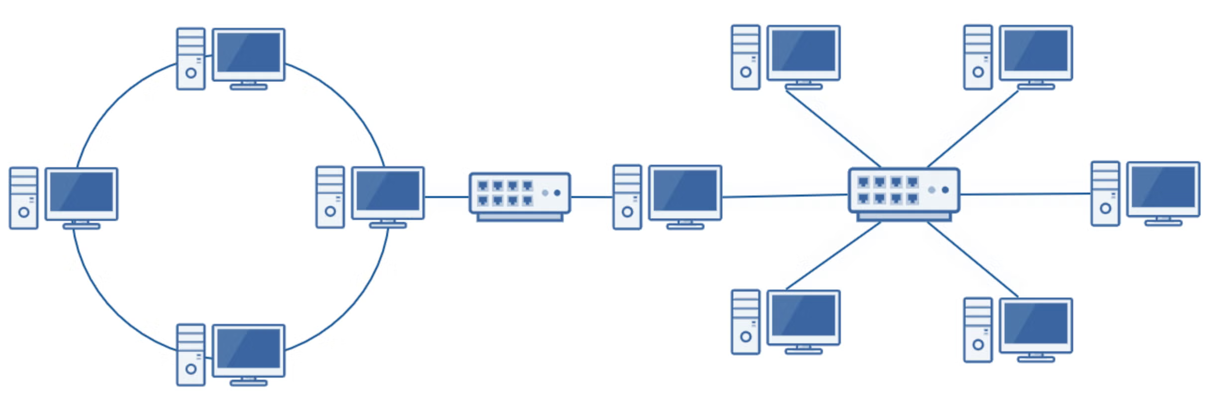
The advantage of hybrid topology is its flexibility—you can adapt the network however you would like. You can combine star and bus, star and ring, or more in whichever way best fits your needs. There’s no one way to create a hybrid topology.
The disadvantage of hybrid topology is that it can easily become complex. With multiple different setups as part of one network, you need to consider the pros and cons of each one.
As the complexity of the network grows, you’ll also need admins who are very knowledgeable and experienced in order to properly manage it—and documentation of this structure will be more important than ever. Because of this, the hybrid topology is labor-intensive, but for some organizations, the benefits outweigh the costs.
Back to topHow to Make a Network Topology Diagram
Diagramming your network topology as a resource for your team and a guide for troubleshooting is easy with a network diagramming tool like Gliffy.
When you launch Gliffy, just select “Network Diagram” from the options listed and you will see all the shapes you’ll need to recreate the physical or logical structure of your network.
Start by pulling all of the components of your network onto the canvas, then group them together as needed. Connect the shapes, add any necessary labels or explanations, make some finishing touches, and you’re done!
For a more detailed tutorial, check out our blog post on how to draw a network diagram.
If you use Confluence for technical documentation, Gliffy is the perfect choice for your IT diagrams. You can create your diagram directly in Confluence without ever leaving the page. Then, all you need to do is save and publish, and the diagram will be right alongside other important information about your network.
You can give it a try for free now, or if you’re not a Confluence user, check out our online diagramming solution and see how Gliffy helps IT teams of all sizes build better documentation.