What is a UML Sequence Diagram?
A sequence diagram, also sometimes called an event diagram, is a type of UML interaction diagram that illustrates the interactions between objects in a system in the order that they occur.
Sequence diagrams are an important type of application architecture diagram to include in technical documentation because they outline system requirements, making them a valuable planning, decision-making, and onboarding resource.
To add a sequence diagram directly to your Confluence documentation, add Gliffy to your Confluence space (it's free for 30 days!):
What is a Sequence Diagram Used For?
Sequence diagrams are most commonly used by technical teams. They represent the details of a UML use case and the logic behind how objects and components interact with each other throughout a process.
Sequence diagrams are often created and used during a future system’s planning phase. Architects and developers use them to visualize how the system should behave and provide a helpful framework to use throughout the design process. However, they can be created any time as a way to document existing systems.
Although sequence diagrams are very technical, they still provide a slightly higher-level view than code itself, so they can also be used to communicate system requirements to business executives and other non-technical stakeholders.
Back to topCommon Sequence Diagram Symbols and Notation
Here are a few of the terms and symbols you will need to know before creating a sequence diagram.
Use Cases
Use cases in UML are specifications of a sequence of events performed by a system, including its variants. It’s usually helpful to define use cases before creating a sequence diagram, as this will provide necessary context for the diagram’s structure.
Scenarios
A scenario is the systematic execution of one specific path. A single sequence diagram can describe just one scenario or multiple scenarios.
Lifelines
Lifelines are vertical lines used to represent objects that send and receive interactions throughout the sequence.
Messages
Messages are communication between objects and are represented with arrows. The type of arrow depends on the type of message:
- Synchronous messages require a reply from the receiving lifeline in order for interaction to continue and are represented by a solid line with a solid arrowhead.
- Asynchronous messages don’t need a reply from the receiving lifeline in order to continue and are represented by a solid line with a lined arrowhead.
- Return messages are sent back to the original sender after a message is received and these are represented by a dashed line with a lined arrowhead.
There are a few other, more specific types of messages, such as “create” and “destroy” messages, but the three listed above are the most commonly used in basic sequence diagrams. Some systems even have reflexive messages, meaning a lifeline sends a message back to itself, which is shown with an arrow looping back to the original sender.
Activation bars
Activation bars are vertical rectangles on a lifeline that make it clear at a glance when each part of the system is active throughout the process. The length of the activation bar depends on the length of activity.
Notes
Notes are not required and are not an official sequence diagram element, but they can be used to provide additional information as needed. Connect notes to objects with a dotted line.
Sequence Fragments
Sequence fragments, a new addition to UML 2.0, provide helpful notation to make sequence diagrams more detailed and accurate. They are helpful when managing complex interactions because of the extra context they provide.
A sequence fragment is a box around a section of the diagram with a label that describes its purpose. Here are some of the types of fragments that you might need in order to accurately describe a process in your sequence diagram.
| alt | The “alt” or alternative fragment represents mutually exclusive alternative paths. |
| opt | The “opt” or optional fragment will either occur or not occur based on the conditions. |
| par | The “par” or parallel fragment represents simultaneous paths. |
| loop | The “loop” fragment repeats multiple times in a row. |
| neg | The “neg” or negative fragment represents invalid interactions. |
| ref | The “ref” or reference fragment indicates an interaction defined on another diagram. |
How to Make a Sequence Diagram
The first thing you will need to do before making a sequence diagram is decide on the tool you will use to create it.
It also may be helpful for you to create a use case diagram first, to provide basic structure and context for the flow of the sequence diagram.
Watch our sequence diagram tutorial to learn how to make your sequence diagram or follow along with the steps below.
Step 1: Find the Right Template (Or Start From Scratch)
When you first open Gliffy, you’ll be faced with the option to use a template. Under the “Software Design & UML” tab you’ll find a sequence diagram template that you can select and edit to fit your needs.
However, you might prefer to start fresh, especially if you want to build a complex structure. If you open a blank diagram, make sure you have the UML shape libraries selected by clicking “More Shapes.”
The remaining steps will guide you through what you’ll need to remember to include as you create your sequence diagram from the beginning.
Step 2: Create and Label Lifelines
Drag and drop your lifelines onto the canvas, then align them with each other and label them all. Make the lines as long as you need to fit the entire sequence.

If your diagram includes lifelines that are created as part of the process and don’t exist at its beginning, you can indicate that by placing the top of that lifeline lower than the rest.
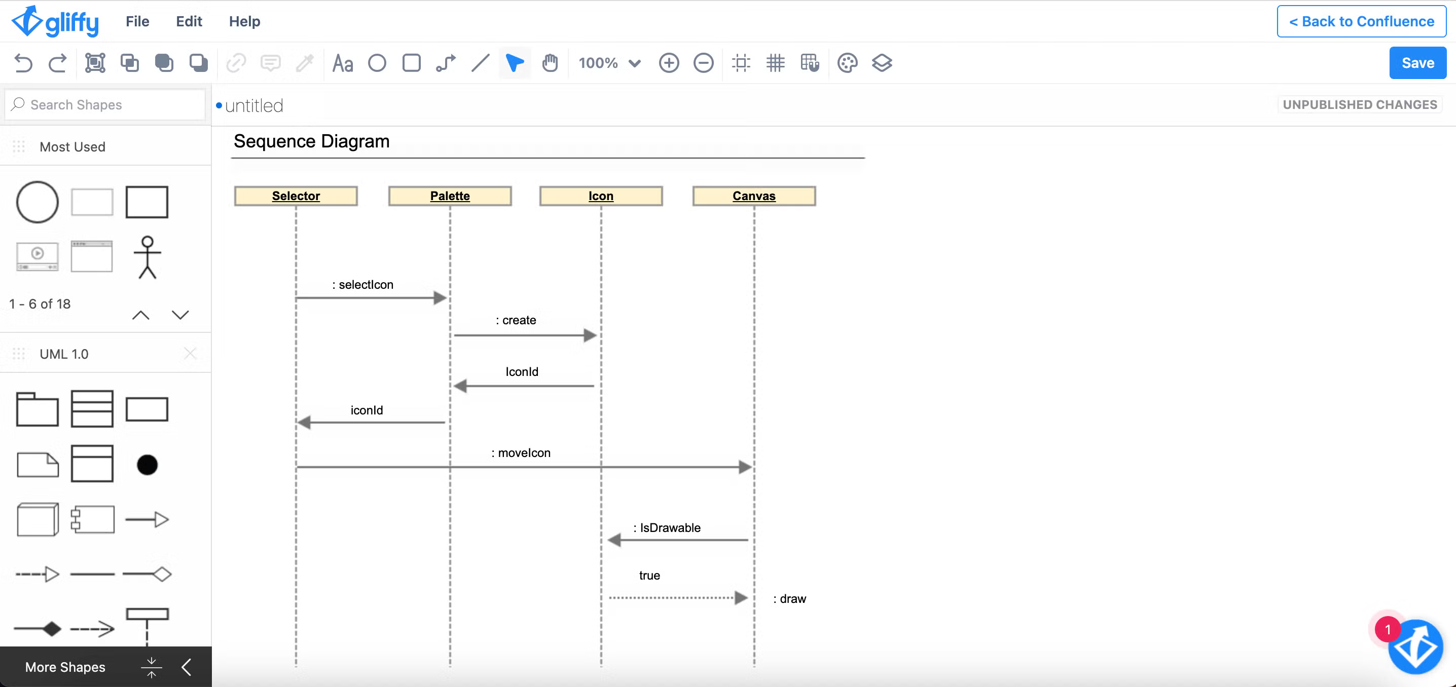
Step 3: Connect and Label Messages
Now it’s time to connect the lifelines with their interactions. Make sure that the messages are in the correct order, with the first message on top and the last one on the bottom.
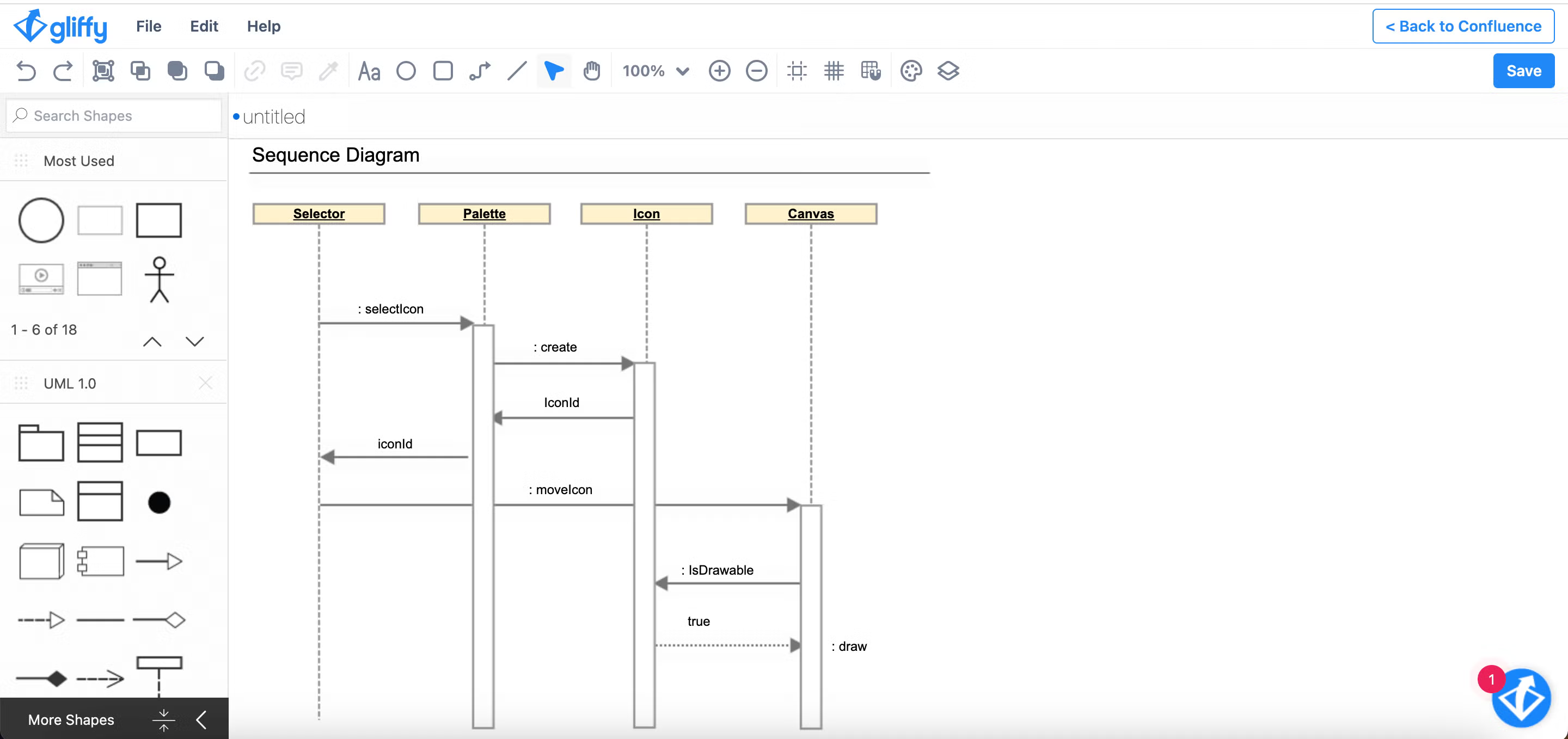
Step 4: Add Activation Boxes
Add vertical activation boxes onto each lifeline to indicate when it is active during the process. You might need to clean up your message arrows to properly align with the activation boxes.
Step 5: Add Sequence Fragments
If your sequence diagram involves fragments, drag in the appropriate frames and place them around the relevant sections of the diagram.
Step 6: Save and Share!
Your sequence diagram is ready! Save and publish the diagram to make it accessible to the rest of your team.
Back to topTry Gliffy, a Sequence Diagram Tool for Confluence
Gliffy makes it easy to document complex systems, whether you are at the beginning of the planning process or documenting an existing system. Start your free trial of Gliffy for Confluence today to bring a visual element to your technical documentation.