What is a Use Case Diagram?
Use case diagrams are a type of UML diagram that summarize the details of a system’s function by depicting outside users’ interactions with it. By visualizing all of the possible actions taken between a system and an external actor, use case diagrams are helpful for system planning and communication.
Different from many other types of UML diagrams, use case diagrams do not show events as they occur in time order and are instead a more broad overview of the system. For this reason, use case diagrams are often accompanied in documentation with other technical diagram types, like sequence diagrams or activity diagrams.
Back to topBenefits of Use Case Diagrams
Use case diagrams are one of the least technical UML diagram types, so they are a great way to communicate high-level concepts about a system to managers or other business stakeholders. They are an effective tool for general functionality analysis without the need to get into the specifics of how those functionalities are implemented on a technical level.
Use case diagrams are also an important part of the system planning process because they allow the team to visualize the system’s functional requirements and translate them into design priorities.
Back to topWhat Are The Main Components of a Use Case Diagram?
Use case diagrams don’t use as many symbols as many other types of UML diagrams. To learn more about UML notation in general, check out our UML diagramming blog.
Use Cases
Use cases are the main element of the use case diagram and are represented by oval shapes. Use cases are the different ways that actors can interact with the system and should always be labeled with an action phrase that indicates the goal of the use case. For example, an online clothing store’s use cases would include checking out a purchase or processing a return.
Actors
Actors are the other primary component of the use case diagram. They are depicted by stick figures in the diagram, but they don’t have to be people, although they often are. Actors can also be organizations as a whole or even other systems.
The only qualifications of an actor are being outside of the system and interacting with it in some way. Actors should also be labeled, but label them with their function or role, like “customer” or “user,” rather than their actual name.
Associations
Associations are interactions either between an actor and a use case or between two use cases. Actor and use case associations are represented by a solid line.
Associations between two use cases, however, are represented by arrows and require a label of either “uses” or “extends.” “Uses” means that one use case is used by another to perform a task. “Extends” means that one use case can be used with another to extend its functionality.
Systems
A rectangle containing all the system’s use cases represents the system itself, so all actors are always outside of it.
Back to topHow to Draw Use Case Diagrams
The fastest and easiest way to draw a use case diagram is with an online diagramming tool like Gliffy. Gliffy for Confluence allows teams that work in the Atlassian ecosystem to document system requirements without ever leaving Confluence or Jira.
Ready to get started? Open a new diagram and follow along with these steps.
1. Find a Use Case Diagram Template
When you create a new Gliffy diagram, you can find use case diagram templates in the “Software Design & UML” templates tab. There are a few different options to choose from, so you can select the one that best fits your needs, or just open a blank diagram and make sure you have the UML shape library selected to build your use case diagram from scratch.
2. Identify All Actors and Use Cases
Who or what interacts with the system, and what are they trying to achieve? Answering this question is the foundation of the use case diagram.
Don’t forget these important tips for identifying actors and use cases:
- Actors don’t have to be people — they can also be organizations or external systems that interact with the system in some way.
- Actors should be labeled by their role (customer, administrator, etc.) rather than their actual name.
- Use cases should be labeled as the goals of the actor.
3. Draw the System
Remember to draw the rectangle that represents the system around all the use cases. Use cases should always be inside of the system, and actors should always be always outside of it.
4. Add Associations
Now it’s time to show how the elements of your system interact with each other.
Don’t forget the types of associations and how to depict them:
- Actor to use case: Use a solid straight line.
- Use case to use case: Use an arrow with the “extends” or “uses” label.
5. Make the Final Touches — Then Share!
Finish adding any extra notes and labels that your diagram might require for extra context. In Gliffy for Confluence, clicking the save button will automatically embed your diagram in the Confluence page you're working on, but you can also share the link to the diagram directly.
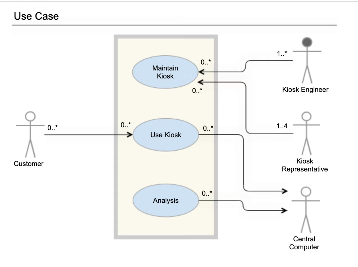
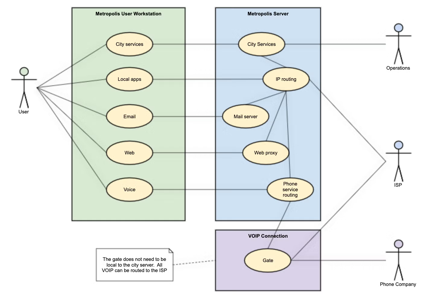
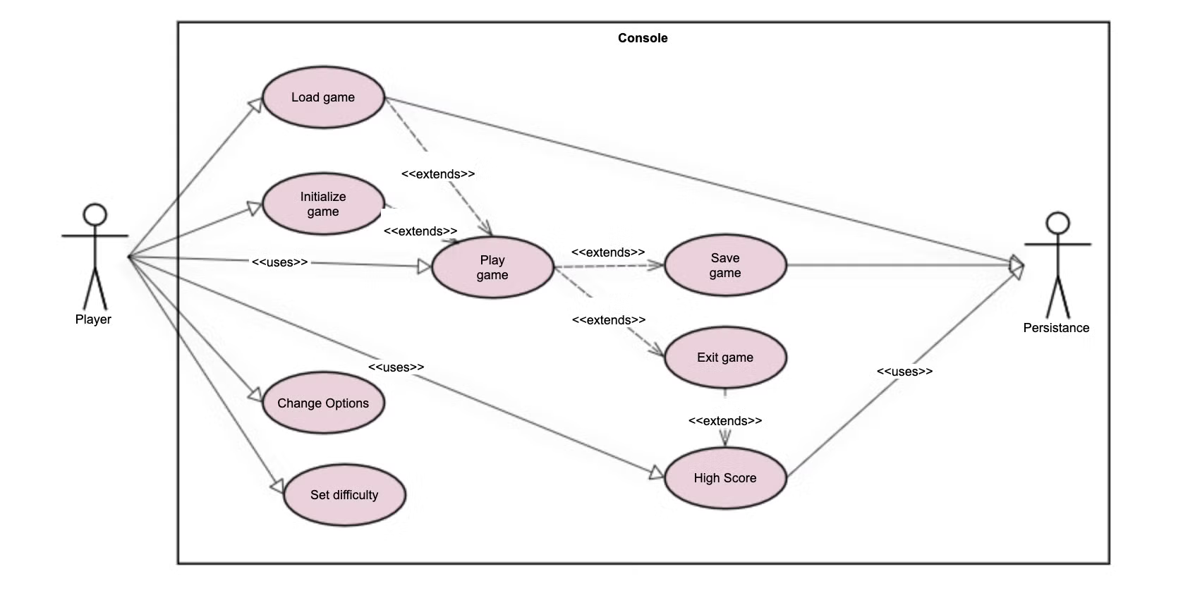
Back to topUse Case Diagram Examples
Here are just a few use case diagram examples for various applications. These examples can all be found as templates in Gliffy for Confluence.
Back to top
Illustrate Your System’s Use Cases With Gliffy
Gliffy makes it easy to communicate important information about systems to technical or non-technical stakeholders and enable cross-functional collaboration. Start your free trial of Gliffy for Confluence today to start drawing your own use case diagrams online.